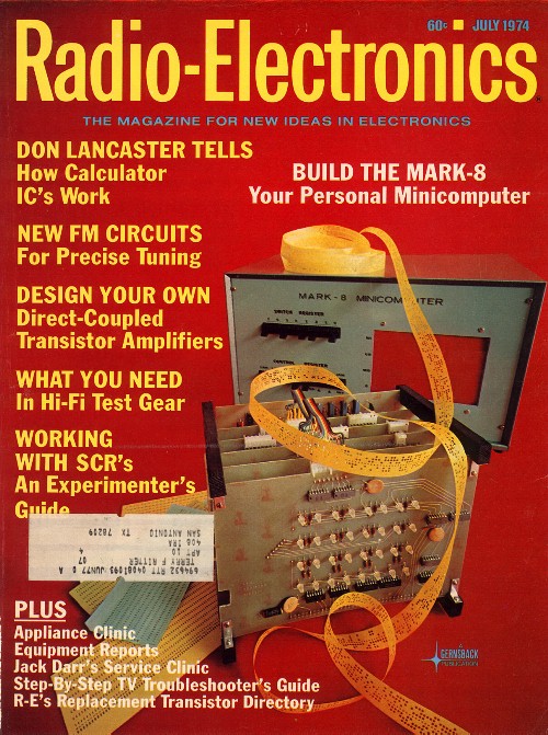
The Mark-8 was the first personal computer.
Before hard drives and printers; before floppy disks and dumb terminals; before the Motorola 6800 and the Intel 8080; there was the Intel 8008, the first 8-bit microprocessor. And in July 1974, Radio-Electronics magazine printed a construction article about building an 8008-based personal computer.
This is the issue that started it all. Before Apple, or even Altair, there was the Mark-8. I built such a computer, and this is my story.
One reason for this page is to document what it is like to have a bare computer and no software at all. This is the process by which raw computation first starts to become something one can use for other work. This sort of development, repeated by many people in many places, is how we got to where we are. Both the equipment itself, as well as the process of developing systems using that equipment, are precursors to the era of computing we see around us.
Even now, a modern processor may be introduced without much software. But almost nobody brings up a new processor without using other computers and their storage and editors to leverage the situation. Every new processor has at least a simple cross-assembler (or even a "C" cross-compiler) that runs on a PC and produces code for download into the new system. Not even computer engineers generally know what home computing was like before there were personal computers.
Writing little test programs
Another reason for this page is that someday somebody just might
want to make a Mark-8 run and do something the way it might have
done originally.
That somebody might be another original user, or a collector, or
even a museum.
(Personally, I think there is a serious need for museums to
demonstrate old technology beyond exhibiting obsolete devices as
amusing visual artifacts.)
In any case, perhaps some of the debug analysis, or some of the
test programs, or the keyboard executives or tape interface code
might be useful steps toward getting a
In the fall of 1974 I had just moved from San Antonio to become a Junior in the Engineering school at the University of Texas at Austin, and I had just enough money to buy a set of boards and enough surplus parts and make them work.
The Mark-8 was not a kit. One could get schematics and a set of circuit boards. Then I had to order the right TTL digital logic chips, many disc capacitors, 32 "1101" 256-bit memory chips (a full 1K bytes!), 16 switches, 32 light-emitting diodes (LED's), and so on. Only then could I solder parts to the boards, and wire things up. The original double-sided PC-boards did not have plated through holes, and often expected the IC or socket pins to connect between runs on the top and bottom. Using sockets would have been tricky, because they had to be soldered both on the top and the bottom of the board, and then the top joint could not be inspected easily. So I did not use sockets, except for the 8008 itself. (Later I did use Molex socket-pins on an add-in 2102 memory board, which gave me a full 4K of main memory!). Of course I also had to design and build the power supplies and interface a keyboard and, very soon, a teletype.
When first built and powered, naturally the computer did
not work.
I had to trace down various errors (often, shorted connections
between IC pins), and replace a few bad parts.
But by October 1974 the computer did work.
This was right at the start of home computing.
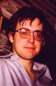
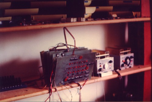
This is my Mark-8. Note the lack of a case, or even a frame to hold the cards. I never made a case, mainly because I always needed to get to the boards. The hardware development never settled down.
Instead of the clear epoxy LED's shown in the magazine, I used red ones, because they were what I could get. Instead of using a backplane, I just wired the boards together with tinned bus wire. The wires in the bus obviously bent every time I needed access to one of the boards, but I had remarkably few problems with the wire breaking.
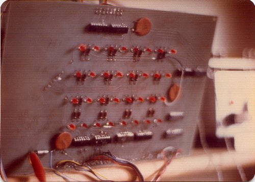
If we look closely, we can see that different LED's have different intensities, so the machine obviously was running when photographed. (There are more convincing pictures later.) As I recall, the top bank of 8 LED's held the high-order 6 bits of the address (H), and the next bank was the lower 8 bits of the address (L). The next lower bank was the 8-bit memory data at the above address (M), and the bottom bank was just a visible output port.
The red alligator clip at the left is 5V power for the audible logic probe which was always at the ready. The yellow and blue wires soldered to that capacitor went to a pulse probe of my own design. This was necessary because the surplus chips I had would die frequently and then I would have to troubleshoot the machine and put in a new chip. This took some time as the chips were all soldered in (except the 8008 itself). To remove an old chip I would chop off the pins with diagonal cutters, then unsolder each pin and clear each hole, one at a time. Then I could put in a new part. That was actually easier than it sounds; the hard part was finding the problem in the first place.
The other wires coming off the bus at the front are a ribbon cable going to the magnetic ROM breadboard, which also held more I/O ports and other things.
The essence of a computer, as opposed to the components which make it up, is the way the design moves data from part to part. Typically, data will flow on a data bus, here 8 metallic wires that carry the value being represented. The following is an attempt to show the buses involved and how they relate to the dispaly values as they appear on the Mark-8 front panel:
"Opcodes," or "operation codes," are the values which tell a computer what to do. Different computers have different instructions, and different values select those instructions. The "set of instructions" in a particular computer represents the basic set of tools from which all results spring. In the beginning, that is all there is.
This is an article I wrote (and hand typed!) in October 1974 for publication, but which never got published. While I certainly hope I have improved my writing in the many years since, the article does give specific suggestions about how to bring up a new or buggy Mark-8.
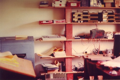
Obviously the lab of a student!
Often I left the machine running a memory test, which would
stop when some problem was found.
One time I walked across the room and touched one of the output port
LED's, felt a spark, and of course the machine stopped.
The ESD (electro-static discharge) had blown one of the TTL chips,
but not the driver for that LED, as one might expect!
Subsequently I got some paper ESD booties from a hospital
emergency room that had a cloth conductive strip which stretched
from inside one's sock to the floor.
That reduced the static problem.
To the left we can barely see two banks of switches. These were just plastic paddle slide switches screwed into cut-off chip shipping rails. One bank controlled the computer (Run/Stop, Step, Store, etc.), and one bank was an 8-bit binary input. I had a lot of switch dirty contact problems.
To the right we see the two power supplies, one each
for +5 volts and -9 volts.
These were linear supplies based on 723 regulator chips, and
they got hot.
But the massive heat sinks in the picture appear to be just
resting on the boxes to cool them off a little better.
At the end, I actually had a little 4-inch AC fan blowing on
the 5 volt heatsink that we do not see here.
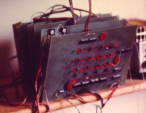
At this time, my version of the Mark-8 consisted of six boards.
Here I have glued some trimpots on the second board; these zeroed the stroke generation circuitry for the oscilloscope display we will see later.
In the beginning, the machine had no nondestructive memory at all. When first turned on, no programs were present. I had to enter a program byte-by-byte, using the eight input bit switches. And as soon as power was removed, all that was lost so I got to do it all over again next time. This got old very quickly.
The first step toward civilizing the computer was to interface an ASCII keyboard to an input port. Although one might think that any reasonable keyboard would have a "strobe" line to indicate a keypress, my first one did not. So I designed a circuit to cause an interrupt whenever the keyboard produced a character. Then, if the computer was running a program which executed a HALT instruction, and if the interrupt switches were set to NOP, a keyboard interrupt would just cause the program to continue. Typically, the next few instructions would pick up the key value before it changed.
Then I wrote a simple "loader" program whose only purpose was to take numeric values in octal from the keyboard, collect them into bytes (3 octal characters per byte) and store them in memory. As a result, I still had to enter the loader program from the bit-switches, but the loader was very short, and after that was running I could just type-in a program as octal, and that was much easier.
This is just about the simplest sort of keyboard loader that one could get, and may be one of the earliest 8008 programs that I wrote (9/26/74). (Naturally there had to have been a few programs earlier, since I would not have seen the motive for having a keyboard loader until I had put in some fairly long programs by switches a few times. Loader E would have been the 5th major loader version.) The keyboard loader provided a way to type a program into memory instead of having to use the front-panel switches to set the value of every byte of a program. The loader was intended to have a minimum of jumps, because jump addresses had to be changed if the program was moved to a new location.
Normally, the computer (under control the loader program) would sit in HALT and wait for a key. When a key was pressed, the keyboard put out a character and my interface hardware caused an interrupt to the computer. Because the setting of the interrupt switches was NO-OP, the interrupt simply ended the HALT condition, so the purpose of the interrupt was timing only. Quickly the computer executed an INPUT instruction (Load A from Port 0) thus picking up the key value. The computer then masked out the lower 3 bits of that value, and shifted them left into an accumulating value. The result was then sent to port 0, the front panel bottom LED row, so that the operator could see the value accumulate. After the first three keypresses, the program would just HALT the computer to await another interrupt. But on the fourth keypress, if the value was ASCII '8', the accumulated value was stored, the memory pointer moved, and the accumulated value cleared to start over with another byte. This is not particularly intuitive, but it was the very first such program I had ever seen.
The line of development of keyboard entry and debug continued later with EXECLOADER and then SUPEREXEC, below.
Still, I had no nonvolatile memory, I had no magnetic tape
storage, and and all this was way before floppies or
hard drives.
The next step was to get some nonvolatile read-only memory
(ROM)!
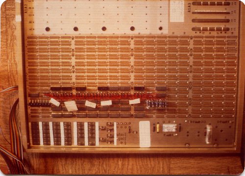
Having read about old mainframe magnetic core ROM, I decided to try and build my own. I conducted a few experiments with some parts I had, and it surprisingly looked like it would work.
Each line was hand-threaded through the appropriate cores to produce a '1'; non-threaded cores produced a '0'. The magnetic-core ROM worked very reliably; better, in fact, than I could possibly have hoped.
Also see the magnetic ROM design and details page.
The breadboard was just a surplus wire-wrap board I got for
a good price because it was fully wired and used.
In the end, removing the wires and getting punctured by
wire-wrap pins was such a pain that I snapped off all the pins
and just soldered to the stumps.
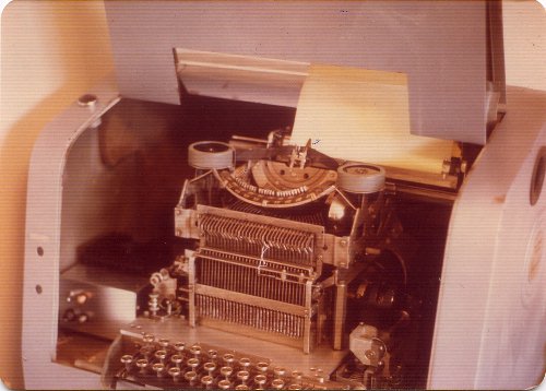
After I got some ROM storage, I had programs on line that converted binary to octal, from octal to characters, and then from parallel to serial for the teletype. I sent the teletype bits out one-by-one, timed by the computer, and that printed characters on a Teletype.
I think this machine was from the 1930's, and the carriage actually moved left and right under the type head, just like a typewriter. The return took long enough that one had to be sure to issue a carriage return (CR) command first, before line-feed (LF), so the carriage would have time to get positioned for the first character on the next line.
I designed and built the interface from the computer to the teletype magnets in the box at the left. Sadly, I got rid of both the big, noisy teletype and the final version of the driver.
An early driver schematic. This is basically a constant-current source, driven by an optoisolator. The second input diode is a front-panel LED to indicate signal. The relatively high voltage assures a fast attack. I believe the zener eventually migrated to across the output, with a series diode: the inductive "kick" has a reverse polarity; by allowing that to rise to a reasonable voltage before dissipating in the zener, we get a fast decay.
Eventually I got some surplus weather printers. These had a drum which rotated very fast under the paper. On the drum was the impression of each possible character for each possible line position. The hammer would drive the ribbon onto the paper at just the right moment and thus mark the paper with the character currently directly underneath; the result was a sort of blurry letter on the top page. These printers were physically smaller, much quieter, controlled by RS-232 serial port levels, and were significantly faster. They also had a cute design which stored serial data on capacitors while the drum revolved and until the character was printed. They were, in fact, a sort of discrete-component dynamic RAM before semiconductor dynamic RAM even existed.
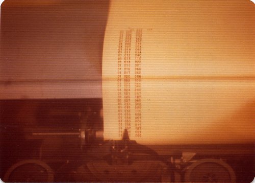
Here is the machine listing memory.
Memory was a maximum of 16KB, so first we have the lower 6 bits (2 octal chars) of register H, then 8 bits of L (3 octal chars), then 8 bits of memory. Each listing line was a separate memory location.
Eventually I added a symbolic interpretation for each
instruction to the right of the memory value, which made the
program much easier to read.
Doing all output with the Teletype also got old quickly.
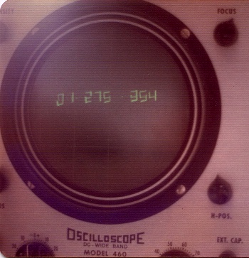
This is an experiment with a real-time CRT display. The CRT was an old, tube-type EICO kit oscilloscope. The computer controlled horizontal and vertical integrator op amps which caused the beam to scan through a fixed box for each character. The computer also controlled the intensity of the CRT, to show the appropriate strokes, all of this under software control in real time.
All the pictures on this page are early, probably early 1975, and the CRT picture reflects the software stroke system. But there was a later version which has no picture. This used hardware sequencing to draw the box and turn on stroke lines. The computer just sent the correct data to the stroke hardware.
Eventually, I found some XY display CRT systems on surplus, and actually bought some. But by this time I did not have the time to use them. And then the price of memory came down so that a dot-mapped display screen made more sense.
I never had even a "dumb terminal" CRT display for the Mark-8.
At this time, companies were still using thermal-printer terminals
in their labs.
CRT "dumb terminals" came later.
The next step in civilizing the computer was to get some sort of data storage on audio tape. I looked at a lot of circuits and tried some things but did not like any of it. In probably May or June 1975, Carl Zettner, another ham, contacted me from San Antonio, and we set up a weekly radio schedule where we started talking about everything.
I cannot remember who came up with what. But I think Carl came up with the idea of sending pulses to the tape recorder, instead of tones. So a short period between pulses might be a '0', and a longer period might be a '1'. My guess is that Carl had had a hardware solution, and that I promoted having software do the timing, and wrote that software. The tape audio output would go almost directly into a Schmitt trigger device (at first a 74121 Single Shot, then a 7413). Then the computer would measure the period between pulses and assign a data value. Surprisingly, it worked.
In the end we had a one-page-per-data-record (256 bytes) file structure with CRC error-checking on each record, and a header record that had a "name" or value for locating the file. Apparently the tape design itself was well advanced by January 1975. I doubt we ever published it.
By February 1976, I was storing many different files on a single tape. When I wanted to read one of those, I could tell the system to read a particular file, and it would skip the other files until it got to the one I wanted, then load it. And if I searched for the last file, then, after the program returned, the following tape area was known to be availble for new storage. The "named" files made the sequential process more convenient for program storage than one might think it could be. Of course, random-access data storage would have been another story: random access really requires some sort of disk.
The resulting 1-chip tape interface was acceptably fast (although, originally, only 400 bps) and incredibly simple. In comparison, other tape storage approaches at the time used fairly complex op amp filtering to distinguish tones, in ways similar to radio teletype or the simple modems of the time. These designs needed far more parts, sometimes required some form of tuning, and often operated at a lower data rate.
This is an early tape loader bootstrap. There is no real file structure, no file naming, no CRC, no dump, just the raw loading of data. Presumably, the tape dump program was saved on tape, and all we needed to do was bring it in. This was probably more experimental than useful, probably based on Carl's first ideas.
This was all in one paper-clipped set. Here we have tape structure, including "named" (actually, numbered) files and per-record error-checking CRC's. It looks like Carl is showing an implementation of the tape system in his personal assembler in January 1975.
I think this was the fully-developed system for use.
Here we have the "documentation listing" for the same system. This is on the old, brown canary teletype paper. (This paper also browned the first two sheets of the above handwritten version.)
From the date (6/30/76), this was probably one of the last things I did on the 8008. I do not know why I was doing this a year and a half after the tape system was working. But it shows that even at the end I was still tightening up the tape system.
An executive typically is a program which takes commands from an operator. Here, that includes the keyboard octal-to-memory function, plus jump to program. In both cases we have to enter locations, so we need those commands too. And when entering data it is convenient to be able to step though memory and only change what needs changing.
A fairly-simple loader, including Baudot TTY output.
This package also tells us about the general system memory structure:
Instead of having commands explictly "wired-in" the executive, this design uses a table of key values and pointers to assoicated code. This could allow the executive to be more easily updated, or perhaps even a new table to be used with the same lookup and control mechanism. (We see that implied in the Lookup routine at 70:014.)
At some point it became clear that keeping a handwritten copy of a program up-to-date was not going to happen. A hand-commented listing was nice alternative, but took a lot of work, and only lasted until the first change. Therefore I developed a program for printing program memory and adding a symbolic representation of each instruction to the listing. While not as clear as a hand-commented listing with drawn lines and goal-oriented comments, the automatic listing could be re-done easily and so had some hope of staying up-to-date.
These listings were done on my weather network TTY's, and are relatively blurry because the metal letters were on a rotating cylinder under the paper. A letter was printed by a print head pressing the ribbon into the paper and the underneath letter at exactly the right time, which is not a prescription for sharp printing. The cheap TTY paper also has oxidized over the years. I tried some things to improve the readability, and while I can make the background lighter, it also seems to make the printing harder to read. And I cannot re-type it because I have no way to check the result for inevitable errors.
In the 8008 architecture, low memory has significant advantages, including fast CALL's to specific low memory addresses through RESTART instructions. But because the RESTARTS typically consumed only part of the available memory, the remaining bits were the obvious place to put vectors (intermediate JUMP's) to particular utilities. So if I wanted to do something new when a utility was called, I could add new code somewhere and change the vector to that code. This was a very flexible approach, an approach we seem to have lost with the universal ability to directly link each routine to the target.
Low memory was a limited resource and usage had to be limited to the most important functions.
All of this was before PC's, so one could not simply use a PC to edit a source code program and then compile it. I never had an editor, or a compiler, or an assembler for the 8008. All my programming was done in raw machine code. That was much easier than it sounds.
For one thing, the 8008 architecture mapped well to octal. The first octal character selected a type of instruction; subsequent characters selected the registers involved. The actual translation of instructions (from concepts to numbers) was fairly easy.
When a processor has a multitude of different address modes for the same instruction, hand-translation can get a lot more complex, but that does not necessarily mean we need an assembler. Maybe we just need a program to produce the desired instruction codes interactively.
I would of course work out an entire 8008 program in pencil on paper, location-by-location, before typing it in. Then I would have to modify the program on that listing because there was no editor where I could fix up the source and type out a clean listing.
In general, new programs have bugs which must be corrected. Programs also have limited original goals, and so will be modified and extended over time if they remain in use. Making program debugging and modification as easy as possible seems a worthwhile goal.
One approach is to allow direct machine-level editing of executable code. That means we may want to delete instructions, in which case the rest of the code should move down (toward low memory) accordingly; or we may want to add opcodes, which should move the rest of the code up. At the end, I developed routines which would insert or delete a location from within a program, and then fix up only the affected JUMPs and CALLs.
So, to add a new one-byte instruction, one would hit "+" to insert a NOP (no-operation) instruction, and the system would automatically fix up any jump offsets which were affected. To add three bytes, one would hit "+" three times, and then we would have the space to type in the instruction without typing over something important. To take out three bytes, one would just hit "-" three times. In all cases, any affected jump instructions in that program would be cleaned up. And since no other programs are supposed to be JUMPing or CALLing into the middle of such code, that took care of most of the problem. (There was also the issue of data tables in memory, which would also move, and so pointers to those locations should change, but values which just happen to be the same value as a table pointer should not change. That meant having some indication in the object code as to the meaning of a value being loaded.)
This was interactive machine-code development with
unsurpassed clarity: No instructions were present or active
that one did not specifically program.
There was no complex operating system.
There were very few surprises.
Last updated: 2002 Feb 21